
A Case Study of Object-Oriented Analysis and Design Methodology - OMT
Unit Title: Object Oriented Analysis and Design
Tutor: Dilip Patel
Author: Li Yi
Course: MSc Computer Science
School: School of Computing, Information System and Mathematics
South Bank University
12/1/1998
1.0 INTRODUCTION
There are many advantages in the adoption of an object oriented approach. The total life-cycle software cost is reduced by increasing programmers’ productivity and by reducing maintenance costs. Software systems are implemented to resist both accidental and malicious corruption attempts. Through reuse and capsulation, it makes a direct and natural correspondence between the world and its model possible. All have been verified by most software developers. That is why Rentsch predicts that "object-oriented programming will be in the 1980’s what structured programming was in the 1970’s".[10] One of the obvious evidences is that more and more old languages such as COBOL have integrated the object-oriented function. New language like Java certainly has object-oriented features.
Object-oriented technique is considered as a good way to solve the "software crisis". This paper shows one methodology of the object-oriented to solve a real case problem.
1.1 Case Background
CSEPDI (Central South China Electrical Power Design Institute) is one of the major power plant design institutes in China. There are more than 10 departments including design, project, archives. Over 800 engineering staff are designing over 10 projects each year for different provinces of the country.
Normally, a project has 5 phases and lasts 4-5 years. After each phase, the main designer of the project should collect all the packets of drawings and calculation sheets to put in the archives. The archivist will record the relevant data of the drawings such as packet no, name, etc., and then put them into proper categories.
The files in the archives are important for the engineers to working on their projects. They are not only the bases for further work of the same projects, but also serve as important references for other similar projects.
What a reference user does is find first the packet no and name of the drawings or calculation sheets from the card index box. Then he/she will write them down and give them to the archivist. The archivist will try to locate packet in the archives. If it is available, the archivist will bring it back to the user. Otherwise, the user will be told where the reference is, that is, who is holding it. It is difficult to ask borrowers to return archives on time because some designers may be on site for a long time. So reference holders are not fined for late return.
The problem is that this important archives system is a manual one. It is time consuming and inconvenient for the designers to borrow the drawings and the calculation sheets.
1.2 Methodology
Rumbaugh’s OMT is selected to build a model for this small and simple case. Of course other methods such as Booch, Jacobson may also be used in this case. The selection of Rumbaugh’s OMT does not mean it is the best method. In fact, there is no single or universally best approach to a solution for the software affliction. [7] The goal of this paper is to use this case to know OMT better.
2.0 OBJECT MODELLING TECHNIQUE
2.1 Rumbaugh’s OMT
Rumbaugh’s OMT method is used here as it had evolved by 1995 before it merged into the Unified Modelling Language. This paper will not detail OMT. Below is just a brief introduction.
The Object Modelling Technique provides three different views of the system: an Object view, a Dynamic view and a Functional view. The Object model describes the object to which something happens (the information flow), the dynamic model describes when it happens (the control flow) and the functional model describes what happens (the process computations).
The method is divided into four phases, which are stages of the development process:[3]
OMT is evaluated according to four categories of criteria: concepts, notation, process and pragmatics. The concepts part addresses the support of the concepts of the object-oriented. The notation part cares about the form of notation in constructing the models. The process part considers the development context, the support for reuse and life-cycle coverage of the method. Finally, the pragmatics part considers nontechnical features of the methods.
Concepts
Although there is no universal agreement on what object-oriented is, the following is a popular accepted point of view for object-oriented [5]:
object-oriented = OID + encapsulation + set-abstraction + inheritance + self-recursion
Rumbaugh claims that the method attempts to show how to use object-oriented concepts throughout the whole of the software development lifecycle. OMT is a truly object-oriented method which supports concepts mentioned above including classes, attributes, inheritance, associations, aggregation, module, concurrency and communication [3].
It supports objects, classes and metaclasses. For association, it supports both nary and ternary ones and it distinguishes between a link and an association. An association could be a class with attributes. An association could be annotated with roles and may have a qualifier. It also supports derived classes, derived attributes, derived associations and constraint between associations. Rumbaugh takes a strong emphasis on associations and relationships almost at a level making these items peers of objects. It supports both single and multiple inheritance. It provides a rich set of aggregation primitives including recursion, qualified and unqualified aggregations, and multilevel aggregation. It supports the expression of inter- and intra- object concurrency and employs an asynchronous model of communication [2].
Notation
OMT supports both logical and physical models. Table 1 shows the models of OMT supports. In fact, OMT views "the world" using three models with different notations: object, dynamic and functional models [2].
Logical |
|||||||
Method |
System |
Component |
Physical |
||||
Static |
Dynamic |
Static |
Dynamic |
||||
OMT |
ER diagram |
DFD/ Event Trace |
ER diagram |
State m/c |
System Arch |
||
Physical model - which is concrete and concerned with the actual structure of the software system
Logical models - which captures the key abstractions of the system
Table 1. Models supported by OMT
The object model is based on Enhanced Entity Relationship - which captures the static structure of a system by showing the objects in the system, relationships between the objects, and the attributes and operations that characterise each class of objects.
The dynamic model is described using Harel State Chart (HSC) for interactive systems. It includes scenarios, events traces, event diagrams and state diagrams.
Functional model is based on a traditional method - data flow diagram. It shows the flow of values from external inputs, through operations and internal data stores, to external outputs.
Table 2 shows properties of OMT notations. OMT has very rich notations. It means that OMT is powerful, but it also means that users will find it difficult to understand and use them [2].
Method |
Expressivity |
Syntax |
Semantics |
Reasoning & Transformation |
Partitioning |
OMT |
Ö |
Ö |
Ö |
Ö |
Ö |
Table 2. Properties of OMT notations
Process
The process steps of OMT method are well defined and flexible. Rumbaugh’s methods provides many useful heuristics to guide the development process. He emphasises the use of scenario walkthroughs to validate the models. Rumbaugh also notes that "Traceability from an element in the original analysis to the corresponding element in the design document should be straightforward since the design document is an evolution of the analysis model and retains the same names."[8].
In the following sections, first, we look at what part of the lifecycle OMT covers, and then discuss the reusability it supports.
Life cycle coverage provides an indication of the completeness and consistence of the methodology. Rumbaugh’s method covers analysis, design and implementation and provides a smooth transition between the various stages of life cycle.
The overall OMT strategy of system development consists of three parts: analysis, system design and object design. Keep in mind that development is iterative as well as recursive. Because a waterfall, step-by-step, rigorously-sequential development cycle is not recommended for my (flexible) case, OMT is suitable for it at this point.
Analysis - In analysis, models that focus on different aspects of what the system is required to do are developed as follows: Object Model, Dynamic Model, Functional Model.
System design - Make the high-level global decisions about the system implementation, including its overall structure.
Object design - Involves further refinement of the initial models to address the requirements of an execution environment.
Table 3 shows the score of OMT coverage life cycle [11]. OMT lacks of supporting enterprise modelling and domain analysis. So, it does not address enterprise and domain reuse.
Method |
Enterprise Modelling |
Domain Analysis |
Requirement Analysis |
Design |
Implement |
Test |
Total |
OMT |
0 |
0 |
5 |
5 |
3 |
2 |
15 |
0 - indicates no mention is made. 1 - indicates that mention is made, but no details are provided.
2 - indicates that mention is made and a definition is supplied.
3 - 2 + at least one example is presented.
4 - 3 + a process is defined.
5 - 4 + heuristics are supplied.
Table 3. OMT’s coverage of life cycle
Code reuse existed before most of us ever heard of Object-Oriented Programming. The next step is black-box components reuse - class in Object-Oriented domain. The higher reuse levels are reuse-oriented organisation like templates, tools and architecture reuse to cover more of the application.
Rumbaugh considers only the reuse of code, with very little practical advice. "Reuse a module from a previous design if possible, but avoid forcing a fit. Reuse is easiest when part of the problem domain matches a previous problem. If the new problem is similar to a previous problem but different, the original design may have to be extended to encompass both problems. Use your judgement about whether this is better than building a new design."
Rumbaugh’s method is well defined and flexible so it can be reused and adapted to meet local requirements. The adaptability of OMT can be improved by the inclusion of guidelines, or heuristics. Walker notes one of the main areas in which the OMT method is lacking - there is no serious attempt to address the systematic reuse of software or design components. [3]
An object-oriented application replaces the coarse-grained procedures with fine-grained objects. The procedure calls are replaced with method calls. These objects, due to their fine granularity may be reused in other applications. However, the objects are still passive: they still require a structure (flow of control) to connect them together. Because this structure is not captured by any object; it cannot be shared with other similar applications. [6] Rumbaugh also discounts the utility of defining classes in isolation for general reuse. "Planning for future reuse takes more foresight and represents an investment. It is unlikely that a class in isolation will be used for multiple projects. Programmers are more likely to reuse carefully thought out subsystems, such as abstract data types, graphics packages, and numerical analysis libraries." Therefore, the higher level reuse should be addressed in OMT.
Pragmatics
There are many pragmatic concerns that influence a method’s usage in the software engineering community.
Support - Several third-party training courses & consultants are available for OMT. It is supported by several training & consultants organisations in Europe and USA. [1] It is important that many low-cost CASE tools to support the method including Select OMT.
Well written book - the book by Rumbaugh is reasonably clear & complete. Although some aspects those relating to integration between the three models are considered to lack consistency, but such criticisms can be levelled at most software engineering books. [1] The book I have read this term is easy to understand and examples in the book show that OMT is practical for the real world.
Accessibility - OMT based on Yourdon method, but with a stronger Object-Oriented bias. It seems to have a small learning curve, but that does not mean that one can learn and use OMT very easily. In some areas it is very complex to learn and use its rich notations.
Language independent - Unlike HOOD, which, being targeted at a specific language, has limited applicability, OMT is language independent. Although in this case, I do not concern this point, it is important for users in real practice. Rumbaugh presents case studies from different domain areas and addresses a wide area - batch, continuous transformation, interactive interface, dynamic simulation, real time system, transaction manager and distributed system.
Future development - OMT is an evolving method. In late 1994 Rumbaugh joined Rational Software Corporation and began working with Grady Booch and in 1995 they were joined by Ivar Jacobson. They produced Unified Modelling Language (UML) which captures the concepts from the OMT, Booch, and OOSE methods. OMT method had evolved to be merged into the UML [9]. All these guarantee the investment in this method will be rewarded.
2.3 Why OMT?
In addition to the methodology’s features mentioned above, I have my own reasons for selecting OMT for the case study:
Popularity - according to a recent survey conducted by the object management group, OMT is currently the most popular of the standardised object oriented development methods. Once I grasp it, it is more likely for this method than other ones to use it again in the future.
Tuition - Rumbaugh’s OMT book has clear steps of how to apply the methodology to real cases and OMT is also the most important method to be taught in OOAD course unit. So, why not OMT? And the tool - Select OMT is available in the lab.
Suitability -.since OMT is derived from a lot of practical works by Rumbaugh et al., and it is being used in numerous projects, it covers more issues than most other methods. It is widely regarded as one of the most complete object-oriented analysis systems so far published. I did not need to worry about if OMT was suitable for my case.
3.0 A CASE STUDY
3.1 Problem Statement
The following problem statement is about a system of lending archives to users to be computerised to enhance the service quality.
Software is to be designed to support a computerised archives lending system. The archives contains drawings and calculation sheets, which users assigned to do a project can order.
The first thing the system does is check the user’s project number and user number. With the right project number identified, the user can borrow drawings through an order. If from the project list the system finds that the user number is a main designer, then he/she can also order the calculation sheets.
In order to find what he/she wants, the user needs to tell the archivist the archive number. For drawings borrowed no date is set for their return, while calculation sheets should be returned before due date. No fine system, however, is necessary for late return. *
Before making an order, the user normally tries to find information about drawings and calculation sheets. This information will tell whether they are available at the archives or to whom they have been lent. Obviously the information system should allow access to many users at the same time.
*To show return date is just give a user the right of requesting the return of the archive by administrative means.
3.2 Object Modelling
OMT requires to construct an object model first in the analysis phase. Based on the problem statement classes and associations should be identified. Next attributes of them will be added to further describe the classes and associations. Then inheritance will be used to combine and organise classes.
3.2.1 Identifying objects and classes
Examination of the noun/noun phrases in the information system for archive lending problem statement yields the tentative object classes listed in Figure 1.
Unnecessary and incorrect classes should be discarded from Figure 1 according to certain criteria. The criteria are whether the classes are redundant, irrelevant and vague ones, or whether they are attributes, operations, roles and implementation constructs. Figure 3 shows the classes eliminated from Figure 1 and Figure 2.

Figure 1. Classes extracted from problem statement nouns
![]()
Figure 2. Classes identified from knowledge of problem domain

Figure 3. Eliminating unnecessary classes from the problem statement
3.2.2 Preparing a data dictionary
A data dictionary for all modelling entities will give each object class precise interpretations, including description of the scope of the class, any assumptions or restrictions on its membership or use. Figure 4 shows a data dictionary for the classes in the current problem.
User ---------- one of staff who is assigned one or more projects. One user with at least one project number, can make orders for the drawings. A user should have idNo, name, deptment and phone.
Calc_User --- a calc_user should be a main designer of a project who has rights to order the calculation sheets.
Drawing ----- drawings approved by CSEPDI for use in a project and stored in archives must have title, projectName, No, designPhase. No return date is set for their return.
Calculation -- calculation sheets approved by CSEPDI for use in a project and stored in archives can only be borrowed by a main designer and have a due date for their return.
Archives ----- a place where the drawings and calculation sheets are stored.
Archivist ----- an employee whose job is to preserve and handle the ordering of the drawings and calculation sheets.
Order --------- a request for borrowing at least a drawing or a calculation sheet.
Project ------- a project done by employee in CSEPDI. A project has projectNo and participant no list.
Figure 4. Data dictionary for the classes
3.2.3 Identify associations between objects
Associations often correspond to static verbs or verb phrases. Figure 5 shows associations for the case. The majority are taken directly from verb phrases in the problem statement. Some associations of the verb phrase is implicit in the statement and some depend on real-world knowledge or assumptions.
Unnecessary and incorrect associations should be discarded. The criteria include associations between eliminated classes, irrelevant or implementation associations, actions, ternary associations and derived associations.
Verb phrases:
The archives store drawings and calculation sheets
Users assigned a project can order
The user can borrow drawings through an order
A main designer can order the calculation sheets
Drawings borrowed with no date set for their return
Calculation sheets should be returned on due date
No fine system is necessary for late return
The information system should allow access to many users at the same time
The user normally tries to find information about the drawings and calculation sheets
Implicit verb phrases:
The Calc_User is a kind of User.
The archivist accepts order and brings out the files
The project will check the project membership input by the user
The project will find if a user is a main designer
Figure 5. Associations from the problem statement
Figure 6 shows an object diagram with the remaining associations. Note that Order is split into Drawing order and Calculation order to accommodate different associations.

Figure 6. Initial object diagram for archives lending system
3.2.4 Identify attributes of objects and links
Attributes are properties of individual objects and are less likely to be fully described in the problem statement. So some attributes are to be supplied from personal knowledge of the application domain. Unnecessary and incorrect attributes are eliminated by specifying objects, qualifiers, names, identifiers, link attributes, internal values, fine detail, and discordant attributes.
Project no is the link attributes between user and project. Figure 7 shows the object model with attributes. Attribute status in Drawing and Calculation class has lots of meanings such as available, return date, holder information. These will be specified in the refine object stage.
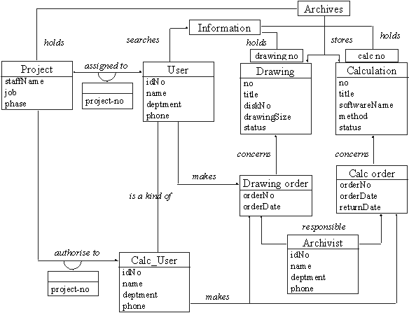
Figure 7. The object model with attributes
3.2.5 Refining with inheritance
It is easy to find some classes in Figure 7 that have similar attributes, associations. The model should be reorganised by using inheritance to share a common structure. Inheritance could be added in two directions: by generalising common aspects of existing classes into a superclass (bottom up) or by refining existing classes into specialised subclasses (top down).
User and Archivist are similar, and can be generalised by Staff. Calc_User is a special kind of User, and should inherit from User. Drawing order and Calc order can be generalised by Order again. Drawing and Calculation have some similar attributes and should be generalised by archive. Figure 8 shows the object model after adding inheritance.
3.2.6 Testing access paths
Trace access paths through the object model diagram to see if they yield sensible results. Each project has an unique project number and each staff working for it is named in the project list. So, a user only needs select the project unique number and input his/her id number. The project will check the user’s right to use the system.
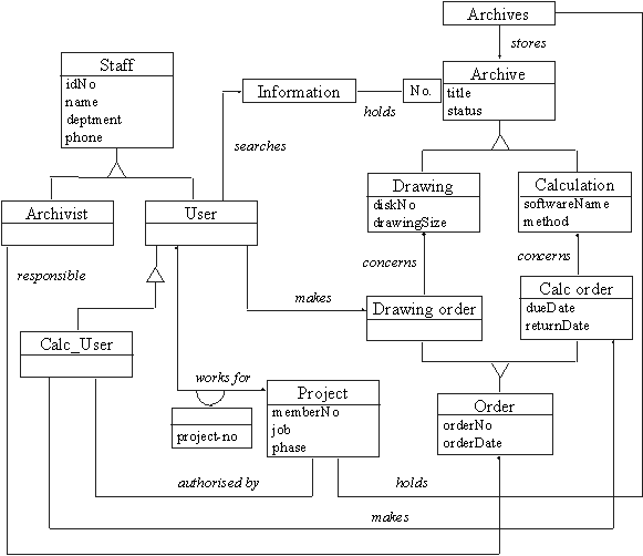
Figure 8. The object model with attributes and inheritance
3.2.7 Iterate and refine the model
The entitle software development process is not one direction way. It needs several iterations to correct some deficiencies. Although this is a simple and small model, it also needs to iterate and refine the model.
Archivist does not seem to enter into the analysis so far. Also Staff is not needed any more.
Basically, an order consists of one or more drawings/calculations. One drawing/calculation is an order_line. So Drawing order should change to DO line, Calc order to CO line. Figure 9 shows a revised object model diagram.
3.2.8 Group classes into modules
Because the model here is a small one, there is no need to break it down into modules.
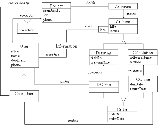
Figure 9. The object model with further revision
3.3 Dynamic Modelling
The dynamic model is important for interactive systems. It shows the time-dependent behaviour of the system and the objects in it. The following steps are performed in constructing a dynamic model for this case.
3.3.1 Prepare scenarios of typical interaction sequences
A scenario is a sequence of events. The screen layout and output format do not affect the initial dynamic model. Figure 10 shows a normal order scenario. Figure 11 shows a scenario with exceptions and Figure 12 shows a normal searching information scenario.
The system asks the user to enter a user ID number; the user enter "1581".
The system asks the user to enter project number; the user enters "F181S".
The system verifies the user number and project number with project list, and asks the user to enter the archive number; the user enters "40-F161S-D05J".
The system dispenses the calculation sheets; the user takes the calculation sheets.
The system asks whether the user wants to continue to order; the user indicates no.
The system asks the user to enter a user ID number.
Figure 10. Normal archive order scenario
The system asks the user to enter a user ID number; the user enters "1581".
The system asks the user to enter project number; the user enter "F171S".
The system verifies the user number and project number with the project list, and indicates that the user has no rights to order and asks the user to renter the project number; the user enter "F181S" which the system successfully verifies with the project list.
The system asks the user to enter the archive number; the user has a change of mind and enters "cancel".
The system asks whether the user wants to continue order; the user indicates no.
The system asks the user to enter a user ID number.
Figure 11. Order scenario with exceptions
The system asks the user to enter the archive number; the user enter "40-F181S-D05".
The system displays the relevant information, and asks whether the user wants to continue; the user indicates no.
The system asks the user to enter the archive number.
Figure 12. Normal searching information scenario
Many other variations can be added: the user enters the wrong ID number, the user enters the expired project number, the user is rejected after three times entering wrong project number, etc. Additional scenarios should be written for administrative parts of the system, such as authorising a new user, opening or closing a project list, adding or deleting an archive.
3.3.2 Identifying events
External events will be identified by examining the scenarios. Internal computation steps are not events, except for decision points that interact with the external world. Figure 13 shows an event trace for an order scenario. Figure 14 shows the events between a group of classes on an order event flow diagram. Figure 15 shows an event trace for a searching information scenario. Figure 16 shows a searching information event flow diagram.
3.3.3 Building a state diagram
A state diagram for each object class with nontrivial dynamic behaviour, shows the events the object receives and sends. Every scenario or event trace corresponds to a path through the state diagram. Object User, Archives, Project and Information are actors that exchange events. Object Drawing, Calculation, Archive, DO_line and CO_line are passive objects that are acted on and do not exchange events. The User is actor, but their interactions with the entry stations are already shown; the User and Archivist objects are external to the system and need not be implemented within it anyway.
Figure 17 shows the state diagram for the archives. Figure 18 shows the state diagram for the project and Figure 19 shows the state diagram for the information.
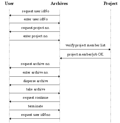
Figure 13. Event trace for archive order scenario
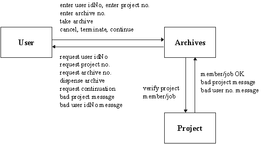
Figure 14. Event flow diagram for archive order
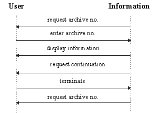
Figure 15. Event trace for searching information

Figure 16. Event flow diagram for searching information
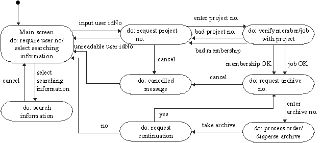
Figure 17. State diagram for class Archives
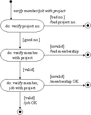
Figure 18. State diagram for class Project
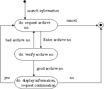
Figure 19. State diagram for class Information
3.4 Functional Modelling
The functional model shows which values depend on which other values and the functions that relate them. Data flow diagrams are useful for showing functional dependencies. Functions are expressed in various ways, including natural language, mathematical equations, and pseudocode. In constructing a functional model for this case the following steps are performed: (the following shows DFD for archives order system, the information system is almost the same)
3.4.1 Identifying input and output values
Because all interactions between the system and the outside world pass through the system boundary, all input and output values are parameters of system events. Input events that only affect the flow of control, such as cancel, or continue, do not supply input values. Figure 20 shows input and output values for Archives application.
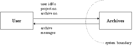
Figure 20. Input and output values for Archives system
3.4.2 Building data flow diagrams
A data flow diagram is usually constructed in layers. Figure 21 shows the top-level data flow diagram for Archives. Figure 22 shows data flow diagram for performing an archive order process.

Figure 21. Top level data flow diagram for archive order

Figure 22. Data flow diagram for performing archive order process
3.4.3 Describing functions
A description of each function should be written in natural language, mathematical equations, pseudocode, or some other appropriate form. Functions in Figure 22 are all clear except order archive. Figure 23 shows description for order archive function.
order archive (user idNo, membership, main designer, archive no, date) à archive, message
if the archive no. is drawing
update borrower to user idNo
if the archive no. is calculation sheets
if main designer is true
write down the return date,
update borrower to user idNo
else
indicate no right message
else
indicate the bad archive no. message
Figure 23. Function description for order archive function
3.4.4 Identifying constraints
The constraint in the archives is: a user can not order the same archive more than one copy at a time.
4.0 CONCLUSION
Much has been learnt from these three models built through OMT methods: 1) The Rumbaugh method fully supports object-oriented concepts. 2) OMT has very rich notations. Emphasis on data structure before functions. 3) The process is well defined and covers analysis, design, and implementation.
OMT is a ternary type methodology. It supports many traditional diagrams from structured methodologies. The concept of using three views to represent a system presented in the OMT is potentially very powerful, and can also be very complex. It is unclear whether the views are to be developed independently of each other, or whether knowledge of one model should be used to influence the construction of another. [3] Some diagram and output formats that end users may prove to be difficult to understand. It would be better to find a way to connect the three views closely and have the traditional diagrams developed to have more object-oriented concepts.
While OMT has encouraging characteristics, the essential problems posed by the very nature of software remain to be tackled - that it is complex, changeable, subject to arbitrary standards, nonvisualisable, and unstable. Whenever an attempt is made to change a bit more for the problem, one needs to go back to the beginning to do almost everything all over again. Clearly OMT is not a complete answer yet. Actually no method is able to show you everything you need to do. So it is important to be aware that OMT is but a tool to be used not something like a rule to be followed.
REFERENCES
[1] Andy Carmichael, (1994) Object Development Methods, Sigs books.
[2] Arnold P., Bodoff S., Coleman D., Gilchrist H. and Hayes F., (??) An evaluation of five object-oriented development methods, JOOP Focus on A&D, pp. 107-121.
[3] Biggs P., (1997) A Survey of Object-Oriented Methods, University of Durham, http://www.dur.ac.uk/~dcs3pjb/survey.html.
[4] Dewitz S., (1996) Systems Analysis and Design and the Transition to Objects, McGraw-Hill.
[5] Graham I., (1994) Object Oriented Methods, 2nd Edition, Addison-Wesley Publishing Company.
[6] Jalal Feghhi, (1996) Web developer’s guide to javabeans, Coriolis Group Books.
[7] Pressman Roger S., (1994) Software Engineering: A Practitioner’s Approach, 3rd Edition, McGraw-Hill.
[8] Rumbaugh J., et al., (1991) Object-Oriented Modeling and Design, Prentice-Hall.
[9] Rumbaugh J., (1997) OMT Summary, Rational Software Corporation, http://www.rational.com/support/techpapers/omt/summary.html.
[10] T. Rentsch. "Object-oriented programming" SIGPLAN Notices. Vol. 17. No. 9. P. 51 Sept. 1982.
[11] The Object Agency Inc., (1995) A Comparison of Object-Oriented Methods, http://www.toa.com/smnn?mcr.htm.